The KM6LYW Radio DigiPi Project


 Download
*
  Ver 1.8-2

  Bookworm
 Pi5 Support
   * Password is currently available to patrons on the KM6LYW Patreon Page Why the paywall? Anything gets you access to the DigiPi image, even a dollar. The point is not to keep the software locked up, but to ultimately throttle the questions and support load. Plus it gives you priority access to design decisions, code contributions and early releases. DigiPi is community driven and open source. I assure you there are no commercial interests, other than beer money. At some point, once development settles down, we'll make a more public release. Please share with friends, but do not post this image online. All of the software carries an open-source license and is freely available, just not all in one place in a bootable image. Thank you for your support.

What is a DigiPi?

The DigiPi is the ultimate hot-spot for all amateur radio data modes, including APRS, ax.25, winlink email, ft8, js8cal, slowscanTV, PSK31, packet and even CW. The implementation is an elegant, inexpensive, low-power, open-source Raspberry-Pi--based amateur radio data transceiver, managed exclusively by web browsers or smart-phone apps, with no bulky keyboards, monitors or complicated wiring. Packet radio Terminal Node Controler KISS interface via wifi or bluetooth Use with xastir, yaac, woad, aprsdroid, and any open-standard KISS apps APRS WebChat interface Send instant messages over the APRS packet network via your web browser APRS Packet Radio Network digipeater Repeat packets heard on 144.390 and 144.800(europe) APRS Packet Radio network IGate Bridge APRS Network to the Internet for email, sms, and other online services Winlink email server Listen for Winlink radio clients requesting to send/recieve email Winlink email client Pat, web-based inbox/outbox email interface ARDOP sound modem to connect to winlink servers world-wide on HF bands Woad Winlink Android app connects to DigiPi via wireless TNC/KISS interface WSJTX FT8 Ultra low signal-to-noise ratio contacts via web-browser/wifi/phone JS8 Call Ultra low signal-to-noise ratio keyboard-to-keyboard via web-browser/wifi/phone FLDigi CW, PSK31, RTTY, Contessa, FSQ, Hell, IFKP, MFSK MT63, Olivia, PSK QPSK, 8PSK, PSKR, THOR, Throb, WeatherFax Slow Scan TV Send/receive images via web-browser/wifi/phone AX.25 Networking Radio connected network protocol used for winlink/node services IP tunnel, with actual address on the internet (44.* for amateur radio) Node Services Run your own bulletin board, or messaging service Connect to other nodes, via intermediate nodes Components Raspberry Pi (Pizero, Pi3 or Pi4) Audio board: Fe-Pi Audio Z v2 *or* Audio Injector Z (edit /boot/config.txt) A simple push-to-talk circuit using a FET, resistor and gpio pin, or A USB cable for radios which support cat/rig control and audio over USB An optional Adafruit 1.3" TFT display Optional LEDs for transmit/receive/bluetooth Pre configured software on DigiPi Rapberry Pi SD card image: Direwolf sound modem and TNC Direwatch display driver LinuxRMS Winlink server Pat web-based winlik email client Web-based mangement interface Bluetooth rfcomm serial port Wifi autohotspot AX.25 Networking, IP, ax25d services Virtual display driver to use interactive apps via web-browser/wifi/phone WSJTX FT8 JS8Call FLDigi qSSTV Linux Node service, netrom, bulletin board, Infocom games Audio driver and mixer settings for audio hats (FE-Pi and Audio Injector) ARDOP modem for 300baud packet on HF bands Rig Control (rigctld) for CAT/audio on USB-connected radios Web-based wifi setup, log viewers, and axcall tty interface

Shopping list

There are two different DigiPi builds. A PTT-circuit build, and a USB-connected build. Radio's with USB ports (ic7300, yaesu991, ic705, etc) do not need all of these parts, just the Raspbery Pi and a USB cable is all you need. If your radio has a conventional PTT circuit/wire (yaesuFTM400, dual band rigs, etc), you'll need the FET/resistor to trigger push-to-talk, an audio card, and will need to fabricate a cable for your radio, see the wiring diagrams below. The screen, while totally cool, is optional and can be attached to either build. Bill of Materials, including PTT circuit A Raspberry Pi, ideally a Pi Zero 2W Amazon Adafruit Chicago_Dist ($15) Watch http://rpilocator.com during the global supply chain crisis and chip shortage. If using USB, a USB "OTG" cable between your pi and radio radio. If NOT using USB, you'll also need the following: Audio hat, one of: Fe-Pi Audio Z v2 [x] 1 Fe-Pi Sound Card without kit WB7FHC ($24) Audio Injector Z Amazon ($20) (edit /boot/config.txt to enable) Stacking header Adafruit(best) Amazon ($3) 2N7000 N-Channel FET Amazon ($2) 100K 1/8 watt resistor Amazon ($2) An optional Adafruit 1.3" small ST7789-based TFT display Adafruit Amazon ($16) Alternative 2.8" large ILI9341 display: Adafruit ($45) (edit direwatchy.py and digibanner.py to enable the larger display) Optional LEDs for transmit/receive/bluetooth Amazon ($9) Ferrite Bead around all the wires between the radio and the audio board ($5)

Hardware Configuration

A step-by-step hardware build video is now available on the KM6LYW Radio youtube channel.
Radio's with USB ports (ic7300, yaesu911, ic705, etc) do not need the follwing wiring, just the PiZero and a USB cable is all you need. All other radios will require a sound card (yaesu ftm400, ftm100, 2980, all HT's). Choose either an "Fe-Pi" or "Audio Injector Zero" audio board, and refer to the respective wiring diagram below. The Fe-Pi is works with the broadest range of radio input/outputs, while the Audio Injector Zero shouldn't be used with radios that have low output (Baofengs, Kenwood HTs), as it introduces a -3dB cut on Line-In. You might also try an audio dongle, but keep in mind they're typically "mic level" and not exactly compatible with a radio-speaker output from an impedance perspective. You might experiment with a voltage divider or inline-resistor to leverage these otherwise affordable USB dongles. They do tend to work well with HT's or low-output-audio radios like Baofengs and Kenwood HTs. Sound-card-builds will also require a ferrite bead around the wires between the radio and the sound card. Supply-chain chip shortages are very real! Get what you can while you can. Watch http://rpilocator.com for up-to-date inventory world wide. This is why I'm suggesting two alternative audio boards:

Choose either the Fe-Pi or Audio Injector Zero diagram


Software Configuration

A step-by-step software configuration video is now available on the KM6LYW Radio youtube channel. If you haven't already, build the hardware here: https://youtu.be/io-YnP0Q-ow This will boot on a Raspberry Pi Zero(packet only), Pi Zero 2W, Pi3, Pi4 or Pi5. You'll need to "unzip" the image first to decompress it. On Linux, it's unzip digipi-1.6-2.zip Then flash it to your SD card. It'll fit on a 4G card with room to spare. Look up how to do this. On Linux, it's dd if=digipi-1.6-2.img of=/dev/sdX bs=4M where sdX is the drive letter of your blank SD card (run dmesg to see). On Windows, try this: https://www.addictivetips.com/windows-tips/flash-sd-card/ On Mac, try this: https://computers.tutsplus.com/articles/how-to-flash-an-sd-card-for-raspberry-pi--mac-53600 Boot the Raspberry Pi with the newly flashed SD card. Wait for the "DigiPi" wifi hot spot to appear on your phone or pc's wifi settings. Connect to the "DigiPi" hot spot with password "abcdefghij" In a web browser, visit "http://10.0.0.5/wifi.php" Enter your home wifi ssid and password and reboot. Once booted on your home network, visit the website http://digipi/. If the host isn't found, login to your router and look for any newly connected wifi devices, and use the associated IP address. Also check to make sure the DigiPi hotspot no longer exists, if it still exists, this is a sign it had trouble connecting to your home wifi. Now that the DigiPi is on your home network, click the "Initialize" link at the bottom of http://digipi/. You need to add your callsign, passwords, grid squares and other localization items to your Pi. http://digipi/setup.php : Keep in mind, once you change a value, you can't use this process to change it again. See /home/pi/localize.sh for the location of all the configuration files and feel free to make edits by hand if you need to add or change anything. Future versions of DigiPi will let you change things repeatedly via the web interface, it's on my todo list. click [Initialize] 
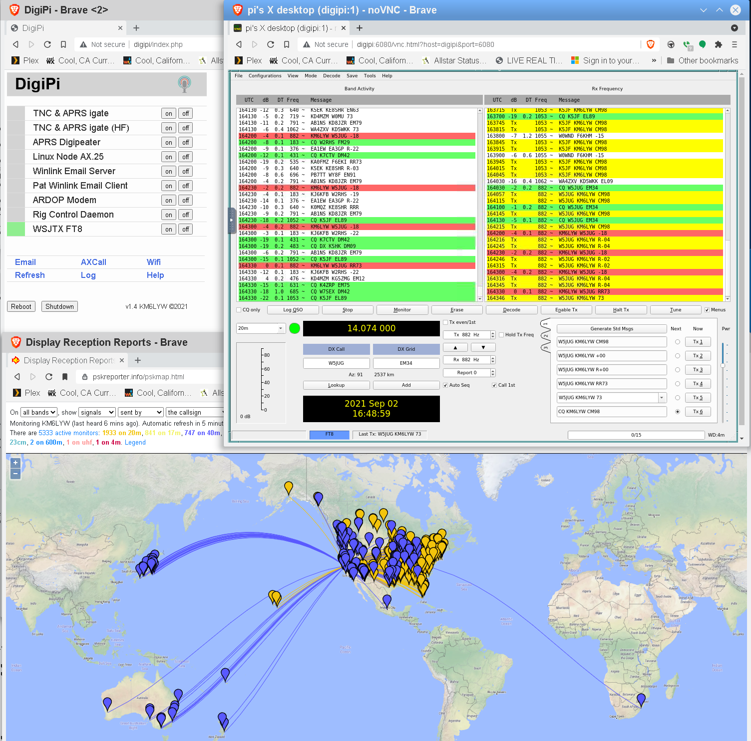
Once changes are made, reboot the DigiPi by clicking [Reboot] at the bottom of http://digipi/. This will boot the system back into firmware (read-only) mode. Enjoy your DigiPi!

Community

http://discord.gg/3X9bMjjwxw (DigiPi live chat) http://groups.google.com/u/2/g/digipi (Primary group/mailing list) http://groups.io/g/digipi/ (old/depricated list, with some good info)

Additional information

The "pi" user password is "raspberry" If not using a USB radio this expects a single audio device, possibly the FE-Pi Audio Z v2, or Audio Injector Z. Edit /boot/config.txt to switch between these two audio hats. The default is currently the FE-Pi. The filesystem is "read only" to prevent SD card wear and so you don't have to do a clean shutdown (just turn off the power is fine). To make modifications, you must "sudo remount" first. If you have a usb-connected radio, no soldering is required. For ft8/sstv/js8call, you'll want to configure your radio from within each app. Yaesu 991 is rig 1035 Icom 7300 is rig 3073 Icom 705 is rig 3085 The GUI apps (js8call, fldigi, ft8, sstv) can be used with a VNC client on your phone. This can be considerably easier to use than a web browser, particularly when it comes to typing, zooming, etc. "VNC Viewer" on Google Play is sufficient. The VNC login parameters are: host: "digipi:5901" or "10.0.0.5:5901" in the field password: "test11" Direwolf will exert a voltage on gpio pin 12 for Push-to-talk. It's up to you to use this signal to short your PTT wire to ground (see FET wiring diagram above). If you hookukp a green led (with 220ohm resistor inline) to gpio pin 16 it will light up when direwolf detects a carrier. If you hookup a red led (with 220ohm resistor inline) to gpio pin 26 it will light up on transmit. At the moment, for USB-connected radios, the transmit LED will not illuminate during transmit (limitation of direwolf, feature request was submitted). If you hookup a blue led (with 220ohm resistor inline) to gpio pin 5 it will light up if you connect a bluetooth device like aprsdroid. I used a 3.2K resistor with this blue led in my implementation because blue leds are oddly bright. If you'd like to change the hostname (and bluetooth name), edit /etc/hostname and also add your hostname to the list next to 127.0.1.1 in /etc/hosts. To use a bluetooth app (aprsdroid, woad) you'll need to pair the device first sudo remount sudo systemctl restart bluetooth sudo bluetoothctl scan on # on phone/wifi device, open bluetooth settings, make visible for pairing # watch for [NEW] Device FC:19:10:F7:55:C8 Device_name pair FC:19:10:F7:55:C8 # click [pair] on phone yes # on bluetoothctl prompt # press [yes] on droid device trust FC:19:10:F7:55:C8 quit # the USB led/icon will illuminate momentarily on the DigiPi shutdown -r 0 When configuring aprsdroid, in connection settings, connection type, select "Bluetooth SPP". Select Channel "1". TNC Bluetooth Device should be "digipi". This image supports a Pi TFT display (1.3 and 1.14" tested) https://www.adafruit.com/product/4393 https://www.adafruit.com/product/4484 Buttons on the display will start the igate or digipeater services. Adjust the volume on the receiver while "tail -f /run/direwolf.log" until the average audio volume is around "50(x,y)." Run alsamixer and adjust the "line" level, while listening to transmitted packets to make sure they're not overdriven, and about the same volume as other aprs radios in your area. the APRS Digipeater service will repeat WIDE1-1 traffic and relay all message-type packets sourced from the internet to targets within 160km of your digipi. Adjust ~/direwolf.digipeater.conf to taste. The device becomes a hotspot if you don't setup your wifi, in which case the ssid is "DigiPi" and the default password is "abcdefghij". You'll find the device at http://10.0.0.5/ . If you're in the field, obviously, this will be its address.

Howto videos and screenshots


DigiPi in FT8 mode connected to Yaesu 991 via USB and Android tablet over wifi

DigiPi installed on Pi Zero with Fe-Pi Audio Z v2 board and adafruit screen


Web/Phone Interface